

Sharing practical student projects and applied learning experiences.
Blink an LED with Arduino
A Step-by-Step Beginner’s Guide
Connecting an LED to an Arduino Uno is the fundamental "Hello World" project for anyone getting started with electronics and embedded systems. While it may seem simple, learning how to properly identify component polarity and integrate a current-limiting resistor is crucial to avoid damaging your components or microcontroller.
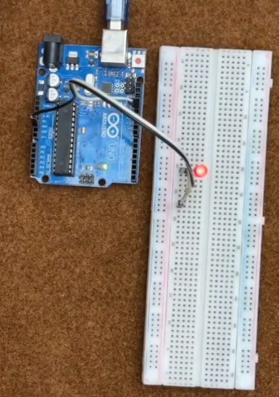
In this guide, we will break down the exact components, wiring connections, and code logic shown in our video to help you build a safe, functioning LED circuit on a breadboard.
Components Required
To follow this tutorial, gather the following basic hardware items:
- Arduino Uno Board
- Solderless Breadboard
- Red LED (5mm)
- 330ohmResistor (Current-Limiting)
- Jumper Wires (Male-to-Male)
- USB Cable (A-to-B) for powering the board
Understanding Your Components Before Assembly
Before placing components on the breadboard, pay attention to these two key technical rules:
- LED Polarity:
- Anode (+): The longer lead. This connects toward the positive signal output pin on the Arduino.
- Cathode (-): The shorter lead. This connects toward the Ground (GND )pin.
- Current Protection:
- LEDs have very low internal resistance. Placing a 330ohm resistor in series drops the excess voltage and limits current flow to a safe level (10mA–15mA), protecting both the LED and the Arduino pin from burning out.
Step-by-Step Breadboard Wiring
Follow the exact steps below to assemble your circuit:
Step 1: Place the LED on the Breadboard
- Insert the LED into two separate terminal rows on the breadboard.
- Note which row holds the Anode (+) (longer leg) and which holds the Cathode (-) (shorter leg).
Step 2: Add the 330ohm Resistor
- Insert one leg of the 330ohm resistor into the same terminal row as the LED's Anode (+).
- Place the other leg of the resistor into an unused terminal row on the breadboard.
Step 3: Connect Jumper Wires to the Arduino
- Positive Signal Line: Connect a jumper wire from the row containing the free end of the resistor to Digital Pin 6 on the Arduino Uno.
- Ground Return Line: Connect a jumper wire from the LED’s Cathode (-) row directly to Digital Pin 13 / GND on the Arduino Uno.
Arduino Code Example
Upload the following sketch using the Arduino IDE to make the LED blink:
C++
// Pin Definitions
const int ledPin = 6;  // LED Anode connected through resistor to Pin 6

void setup() {
  // Initialize digital pin 6 as an output
  pinMode(ledPin, OUTPUT);
}

void loop() {
  digitalWrite(ledPin, HIGH);   // Turn the LED ON
  delay(1000);                  // Wait for 1 second
  digitalWrite(ledPin, LOW);    // Turn the LED OFF
  delay(1000);                  // Wait for 1 second
}
Testing Your Setup
- Connect your Arduino Uno to your computer using the USB cable.
- Select your board (Arduino Uno) and COM Port in the Arduino IDE.
- Click Upload.
- Result: Your LED will begin blinking continuously at 1-second intervals!
Key Takeaways
Always identify the longer leg as the Anode (+) and the shorter leg as the Cathode (-).
Never connect an LED directly to a 5v pin without a current-limiting resistor (220ohm – 330ohm,)
- Breadboards make rapid prototyping solderless and easy once you understand how rows are interconnected..
Comments (0)
No comments yet. Be the first to start the discussion.